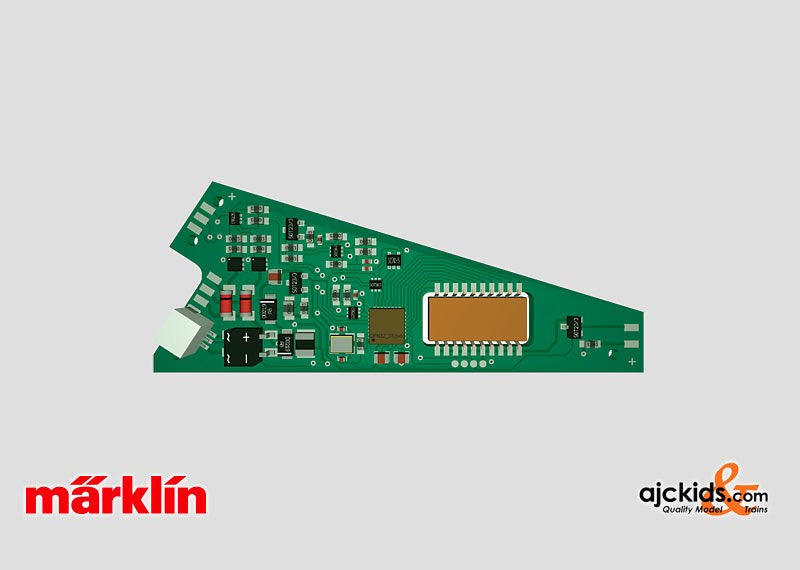
Marklin 74461 - Digital Decoder C-Track (is now 74462)
This decoder has been replaced by the Marklin 74462
This decoder can be installed in all C Track turnouts with electric mechanisms. It can be used with the digital formats Motorola and also with DCC. Connections are made with plug-in contacts, for Märklin and Trix C Track turnouts. An address can be set with coding switches (Motorola Format 1 to 320 / DCC Format 1 to 511), and can also be set on the programming track.
Turnout lanterns can be connected and can be controlled (soldering skills required). A digital decoder can be installed at the same time as the electric turnout mechanism or can be installed later. The decoder is easily connected with plug-in contacts and can have a custom address set for each turnout. The digital power supply for the decoder can be taken directly from the track current contacts on the turnout. This means you can have a complete digital turnout that can also be used on temporary layouts.
Charlie's Tips: The 74465 digital decoder is used with the Marklin 24630 three-way turnout with 2 of the Marklin 74490 or Marklin 74491 electric mechanisms. The main difference with the well known Marklin 74460 decoders is that this decoder also can understand the DCC digital format.
The above image shows how to connect the turnout decoder. The brown and red wires get connected with the brown (outer rail, marked "0" on the track) and red (center stud rail, marked "B").
This is how the decoder gets its digital signal.
The yellow wire also connects to the center rail, and feeds power to the turnout motor.
The turnout lantern Marklin 74470 (is not included with this decoder) can be connected to the decoder, and get its power from the decoder. You will have to solder the two wires onto the tabs on the decoder. You can also power the turnout lantern seperately, with a lights circuit that you may have, using a maximum of 16 volts.
You can also power the turnout from a sepearte power circuit. This is nice when you have a large layout, and plan to switch several turnouts at the same time. In this setup, it does not put a power drain on your digital circuit.
The diagram warns not to connect the yellow to the digital circuit. What they mean to say is:
Do not connect the yellow to the transformer (as depicted) AND ALSO connect it to the digital circuit.
If you did that, you would be putting the max 20 volt DC power (yellow and brown) directly to the digital output (red and brown). That is a nono, booboo and bad for everyone, especially your digital controller.
EAN/UPC: 4001883744612


